Jump to a question in this guide
- What does the heater do before hot water reaches the shower?
- Is yours a storage tank, tankless unit or heat-pump heater?
- What happens inside an electric storage tank?
- How does a gas storage heater transfer heat to the water?
- Why does a heat-pump water heater need an air route and a drain?
- Why are stored volume and recovery different?
- How does a gas tankless heater warm passing water?
- Why can one tap be slow while another runs out of hot water?
- What are sediment, scale and the anode doing?
- Why is the heater setting different from the water at a tap?
- What does a display message or operating mode tell you?
- Which signs need service, and when should you leave immediately?
- What care belongs in a model-specific plan?
- Which manual and dates should you keep?
- What should a useful service record actually say?
- What should you ask before replacement or a new-home handover?
- Identify both the water-heating form and what supplies the heat; a tank shape does not settle the fuel.
- Stored reserve, recovery and the route to a fixture answer different hot-water complaints.
- Use model-specific care and clear service findings; leave hazardous access, adjustments and tests to qualified service.
12 picture lessons appear beside the questions in this guide. Use them to understand the explanation, then consider what it means for your home.
What does the heater do before hot water reaches the shower?
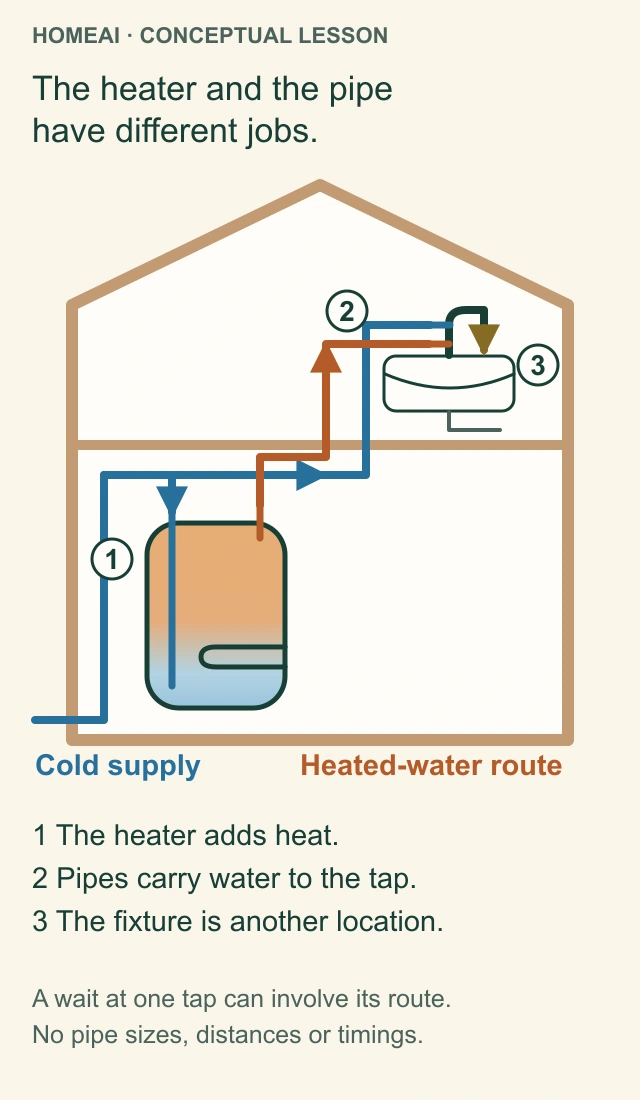
A shower that turns cool sooner than usual can leave you wondering whether the tank is too small, a part needs attention or several people simply used hot water close together. Understanding the heater helps you describe the change before paying for a repair or replacement. Start with two jobs: the appliance adds heat; the household piping carries water to the place where you use it.
The heater and the pipe have different jobs.
Water heater, distribution pipe and fixture. The heater adds heat; the pipe carries water to where it is used. A delay or change at one tap needs that route considered as well as the heater.
Heater
The tank symbol represents a heat source and stored supply. It is not a record of the home’s actual appliance or connections.
Distribution route
The heated-water line travels to the fixture; water already in that route can affect when hot water arrives. This simplified drawing omits other branches, valves, drains and any recirculation arrangement.
Fixture
The tap is a separate point in the system. A change at one fixture can need a different assessment from a change throughout the home.
Drawing boundary
Colours distinguish conceptual routes, not actual pipe materials, approved installation or measured temperatures. No timing, pipe size or repair is prescribed.
Explore the named parts
- Heater
The tank symbol represents a heat source and stored supply. It is not a record of the home’s actual appliance or connections.
- Distribution route
The heated-water line travels to the fixture; water already in that route can affect when hot water arrives. This simplified drawing omits other branches, valves, drains and any recirculation arrangement.
- Fixture
The tap is a separate point in the system. A change at one fixture can need a different assessment from a change throughout the home.
- Drawing boundary
Colours distinguish conceptual routes, not actual pipe materials, approved installation or measured temperatures. No timing, pipe size or repair is prescribed.
The heater and the pipe have different jobs.
Water heater, distribution pipe and fixture. The heater adds heat; the pipe carries water to where it is used. A delay or change at one tap needs that route considered as well as the heater.
- Heater
- The tank symbol represents a heat source and stored supply. It is not a record of the home’s actual appliance or connections.
- Distribution route
- The heated-water line travels to the fixture; water already in that route can affect when hot water arrives. This simplified drawing omits other branches, valves, drains and any recirculation arrangement.
- Fixture
- The tap is a separate point in the system. A change at one fixture can need a different assessment from a change throughout the home.
- Drawing boundary
- Colours distinguish conceptual routes, not actual pipe materials, approved installation or measured temperatures. No timing, pipe size or repair is prescribed.
Read all the diagram text
- HOMEAI · CONCEPTUAL LESSON
- The heater and the pipe have different jobs.
- Cold supply
- Heated-water route
- 1 The heater adds heat.
- 2 Pipes carry water to the tap.
- 3 The fixture is another location.
- A wait at one tap can involve its route.
- No pipe sizes, distances or timings.
- The heater and the pipe
- have different jobs.
- 1
- 2
- 3
- 1 The heater adds heat.
- 2 Pipes carry water to the tap.
- 3 The fixture is another location.
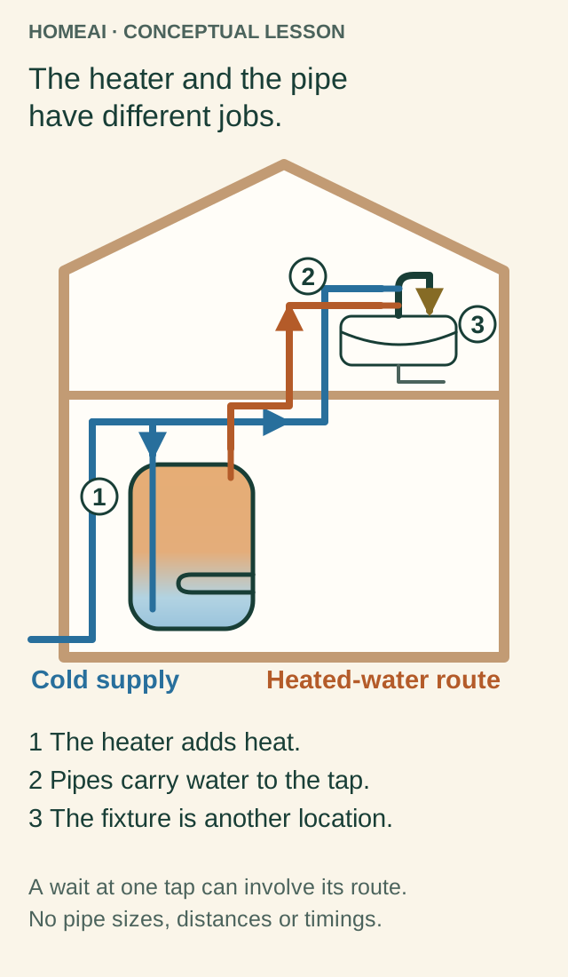
Cold water reaches the heater through its supply connection. Heated water leaves through a different connection and travels along the hot-water piping toward a tap, shower or appliance. A shower also has a cold supply so its controls can mix the two. A problem noticed at the shower can therefore involve the heater, the route or the fixture, rather than one interchangeable “hot-water problem.”
Some homes have an additional hot-water return pipe and circulation controls. Others have point-of-use equipment, more than one heater or a system that also serves space heating. Identify those arrangements from the actual equipment and records. Nearby pipes do not all perform the same job. The separate hot-water circulation guide follows a return loop in more detail.
Sources for this chapter
Is yours a storage tank, tankless unit or heat-pump heater?
Separate the way water is held from the way heat is supplied. A storage heater keeps a reserve of heated water in a tank. A tankless heater heats passing water rather than keeping that same reserve. Either can use different energy arrangements: a cylinder does not establish its fuel, and a wall cabinet does not automatically mean gas.
An electric resistance tank uses heating elements. A gas storage heater uses a burner and a route for combustion gases. A heat-pump water heater uses electricity to move heat from air into stored water; a hybrid model can also have resistance elements. Tankless equipment can heat water with gas or electricity. These differences explain why a generic “water-heater service” checklist can miss important parts.
Use a safely readable external rating plate and the manufacturer's matching instructions to settle the identity. Keep the manufacturer, exact model and serial in your private home file. Leave covers closed and do not reach around hot, wet or suspect equipment to improve a photograph. If the label is inaccessible, ask the service provider to identify it.
Sources for this chapter
What happens inside an electric storage tank?
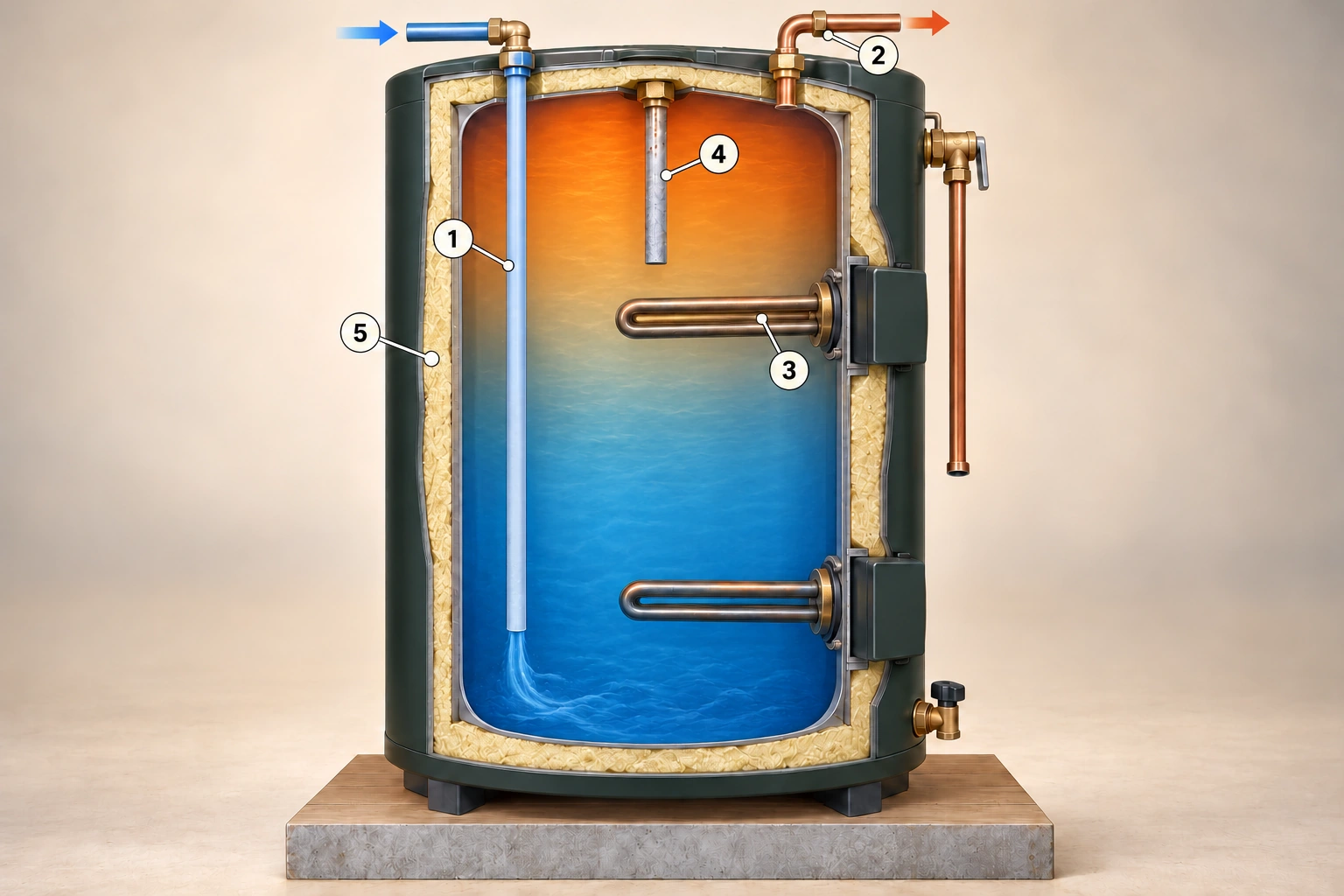
In the illustrated top-inlet arrangement, cold water enters a long internal pipe called a dip tube. Its job is to carry incoming water low in the tank. Hot water leaves through a separate outlet near the top. The vessel is full during normal operation: warm and cool colours explain different temperatures, not an empty space, two different liquids or a dividing wall.
Electric storage: inlet, heat and corrosion protection
Dip tube, hot outlet, immersion elements, anode and insulation perform different jobs. The filled tank stores heated water while its controls call for more heat. The cutaway shows one top-inlet two-element arrangement; actual sequencing and connections follow the model. The relief-discharge pipe is shortened here, so its complete installed route and termination are omitted.
1 · Dip tube
The internal tube carries incoming cold water low in this top-entry example. Bottom-entry and other designs differ.
2 · Hot outlet
Heated water is withdrawn from the upper part of the full vessel. Colours illustrate temperatures, not separate liquids or an air gap.
3 · Immersion element
An element supplies heat when its controls energise it. The presence of two elements does not establish that both run together.
4 · Sacrificial anode
This separate component helps protect covered tank designs against corrosion and can be consumed over time. It is not a heater or an inlet.
5 · Insulation
The pale layer slows heat loss from the tank; the outer jacket and inner vessel have different jobs. Keep access covers closed.
Explore the named parts
- 1 · Dip tube
The internal tube carries incoming cold water low in this top-entry example. Bottom-entry and other designs differ.
- 2 · Hot outlet
Heated water is withdrawn from the upper part of the full vessel. Colours illustrate temperatures, not separate liquids or an air gap.
- 3 · Immersion element
An element supplies heat when its controls energise it. The presence of two elements does not establish that both run together.
- 4 · Sacrificial anode
This separate component helps protect covered tank designs against corrosion and can be consumed over time. It is not a heater or an inlet.
- 5 · Insulation
The pale layer slows heat loss from the tank; the outer jacket and inner vessel have different jobs. Keep access covers closed.
Upper and lower immersion elements extend into the water. Electricity supplies heat through an element when its controls energise it. The thermostats and electrical connections sit outside the water vessel, behind protective access covers. The two-element cutaway identifies the parts without claiming that both are energised together. The actual model's controls govern their operation; one-element and bottom-entry designs also exist.
The outer layers have different jobs. The inner tank holds the water, its lining helps protect the steel, and surrounding insulation slows heat escaping into the room. The outer jacket encloses the assembly. A mark on that outer case cannot show the condition of the concealed lining or establish remaining service life.
The slim sacrificial anode is another distinct part. It helps protect the tank against corrosion by being consumed over time in designs that use it. It is neither the dip tube nor a heating element. The illustration explains these relationships; it is not an instruction to remove covers, expose wiring or open the tank.
An electric resistance tank can suit a home that wants a stored reserve without a burner, combustion-air route or flue. It still needs an appropriate electrical supply, space and service access. Its reserve and heating capability must suit the household; an electric fuel label does not remove water-side, anode or protective-component care.
Sources for this chapter
How does a gas storage heater transfer heat to the water?
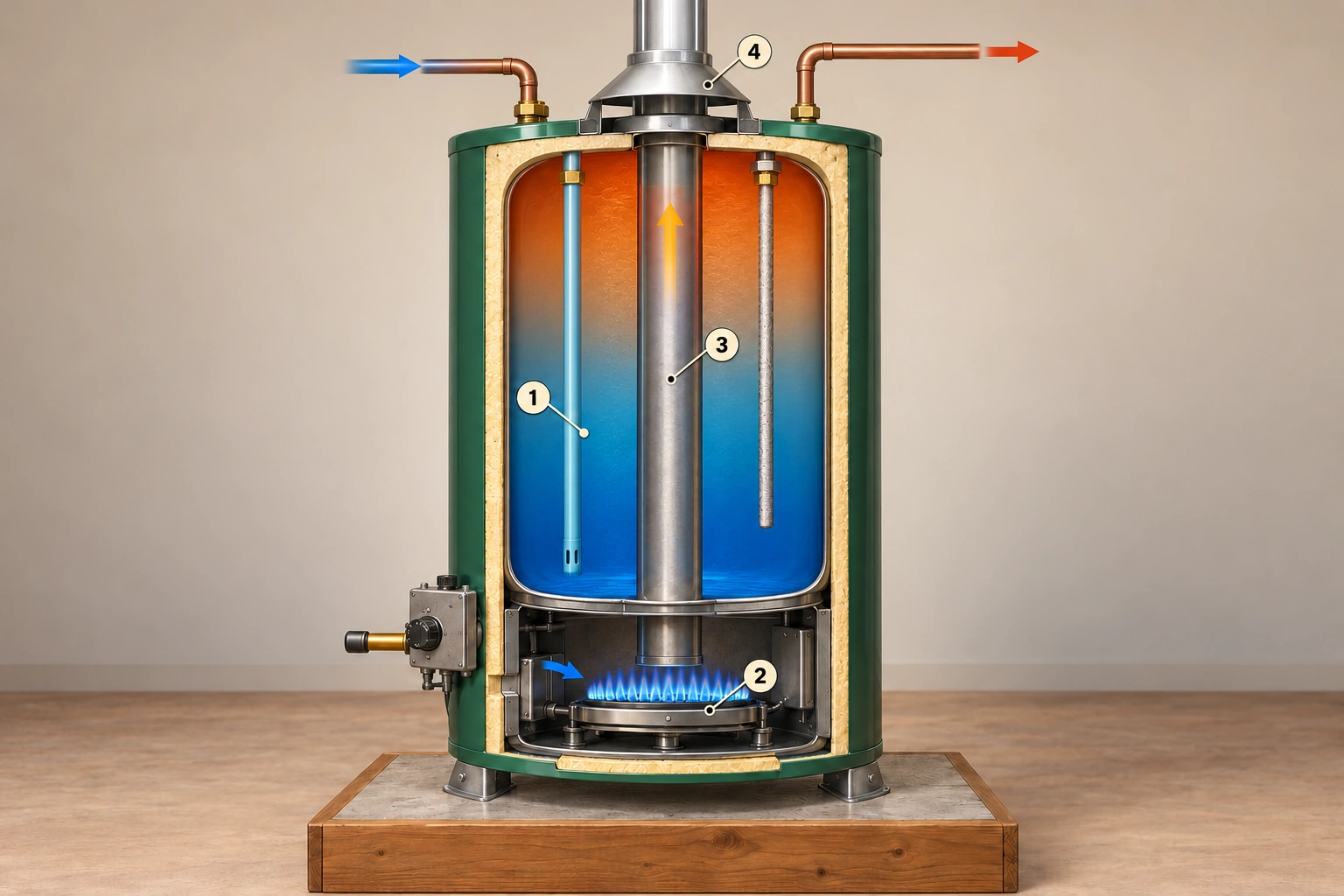
In this natural-draft gas example, a burner sits below the water vessel. Combustion releases heat, and hot combustion gases travel through the internal flue before leaving through the vent system. Heat crosses metal surfaces into the stored water. The water path and combustion-gas path are separate: the tank is not meant to fill with the burner’s exhaust.
Gas storage: heat crosses metal into the water
Stored water and combustion gases follow separate routes. The burner heats through metal surfaces while combustion gases travel in the flue toward the draft hood and vent. This isolated atmospheric-type study omits household connections and protective components; it is not the arrangement of every gas heater.
1 · Stored water
The coloured vessel is full of water in normal operation. The cold inlet and hot outlet are separate from the combustion path.
2 · Burner
The burner is in a dry chamber below the water vessel. Flame and exhaust do not belong in the household water.
3 · Flue
The separate central passage carries combustion gases through the heater. Metal surfaces transfer heat while keeping those gases apart from water.
4 · Draft hood
The hood and its air gap belong to this atmospheric example. Power-vented and direct-vented arrangements differ; actual combustion air and venting need their own professional assessment.
Explore the named parts
- 1 · Stored water
The coloured vessel is full of water in normal operation. The cold inlet and hot outlet are separate from the combustion path.
- 2 · Burner
The burner is in a dry chamber below the water vessel. Flame and exhaust do not belong in the household water.
- 3 · Flue
The separate central passage carries combustion gases through the heater. Metal surfaces transfer heat while keeping those gases apart from water.
- 4 · Draft hood
The hood and its air gap belong to this atmospheric example. Power-vented and direct-vented arrangements differ; actual combustion air and venting need their own professional assessment.
The gas control and thermostat govern the burner. A draft hood and vent connector are recognizable parts near the top of this particular arrangement. Air for combustion must also reach the appliance through its intended route. Here, “atmospheric” means the heater uses natural draft: hot exhaust rises through its intended vent route. The illustrated heater differs from a power-vented or direct-vent design, so its air supply and exhaust arrangement cannot be copied onto every gas tank.
That is why service involves more than checking whether the water becomes hot. Ask which combustion-air, burner and vent-system questions the assignment covers, as well as the water-side components. Keep stored belongings and flammable products away from the appliance as its instructions require. A quiet heater, a flame seen through a window or a silent CO alarm does not establish that its combustion and venting are safe.
Gas storage can suit a home seeking a heated reserve with a suitable gas supply and an assessed combustion and venting arrangement. That water reserve is useful before the next heating cycle has restored all the heat used. The tradeoff is additional fuel, air and exhaust equipment to maintain; an existing gas connection or chimney does not establish that a replacement will fit safely.
Sources for this chapter
Why does a heat-pump water heater need an air route and a drain?
A heat-pump water heater takes heat from air and transfers it to stored water. It still uses electricity, but moving heat is a different job from producing heat directly with a resistance element. In the illustrated integrated heater, the fan and heat-pump assembly belong to the air-and-heat route above the tank; the household's drinking water remains within its water circuit.
The heat-pump head needs an air route
Filter, air-side coil, compressor, fan and condensate drain. Air moves across the coil as the heat-pump process transfers heat toward stored water. This close-up identifies generic head components; it does not locate a condenser inside the tank. The separate cycle diagram follows the refrigerant jobs, and the actual model determines component positions and drain routing.
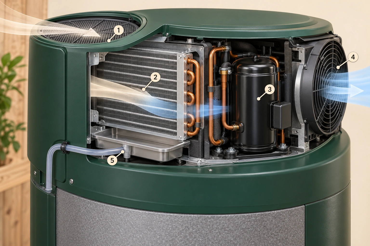
1 · Intake filter
The mesh identifies the incoming-air filter job in this conceptual head. Keep the actual intended opening available and use its model-specific care instructions.
2 · Air-side coil
The finned coil exchanges heat with the moving air. The air route and household water route are separate.
3 · Compressor
The compressor raises refrigerant pressure and temperature as part of the closed heat-transfer cycle. This picture does not show the complete refrigerant pipe arrangement.
4 · Fan and outlet
The fan moves air through the head. The blue ribbon explains cooler leaving air conceptually; it is not a measured temperature or evidence of a particular model’s operating mode.
5 · Condensate connection
The tray collects liquid at the air-side coil and has a separate drain connection. The short line is shown only in part, with no installed termination, trap or homeowner cleaning procedure specified.
Explore the named parts
- 1 · Intake filter
The mesh identifies the incoming-air filter job in this conceptual head. Keep the actual intended opening available and use its model-specific care instructions.
- 2 · Air-side coil
The finned coil exchanges heat with the moving air. The air route and household water route are separate.
- 3 · Compressor
The compressor raises refrigerant pressure and temperature as part of the closed heat-transfer cycle. This picture does not show the complete refrigerant pipe arrangement.
- 4 · Fan and outlet
The fan moves air through the head. The blue ribbon explains cooler leaving air conceptually; it is not a measured temperature or evidence of a particular model’s operating mode.
- 5 · Condensate connection
The tray collects liquid at the air-side coil and has a separate drain connection. The short line is shown only in part, with no installed termination, trap or homeowner cleaning procedure specified.
Inside the sealed heat-pump circuit, a working fluid called refrigerant absorbs heat at the air-side coil, the evaporator. The compressor raises its pressure and temperature. A second heat exchanger, the condenser, transfers heat from the refrigerant to the water. An expansion device then lowers the refrigerant's pressure and temperature so it can absorb heat again. These four jobs repeat within the refrigerant circuit; household water follows a separate route.
Follow the heat-pump loop
Air-side coil, compressor, condenser and expansion device. Refrigerant circulates through these jobs while household water remains separate. The drawing identifies the heating cycle without locating the condenser inside a particular appliance.
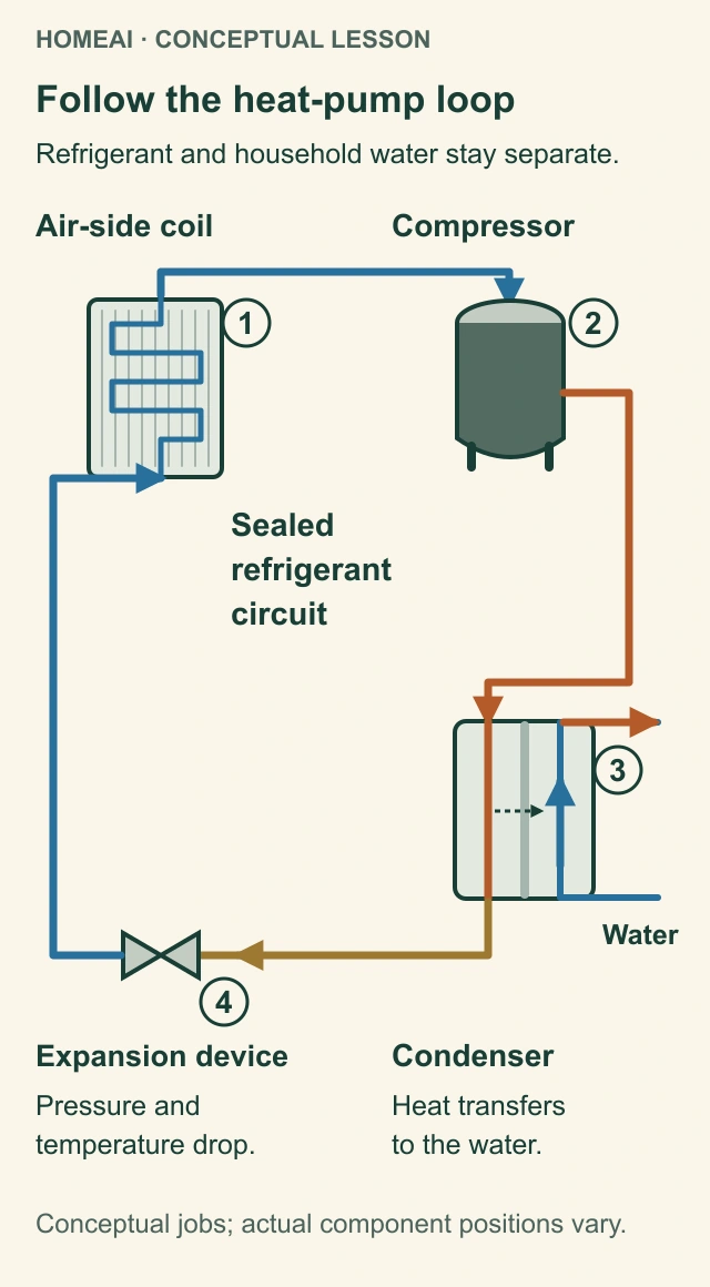
Air-side coil
Refrigerant absorbs heat from air at the evaporator. The fan moves air; household water does not flow through this air route.
Compressor
Compression raises refrigerant pressure and temperature. Electricity runs this part of the heat-transfer process.
Condenser
Heat crosses exchanger surfaces from refrigerant to water. The short dashed arrow marks heat transfer, not a fluid connection. In this concept, water enters at the lower right stub and leaves at the upper right stub; no model-specific condenser construction is shown.
Expansion device
Pressure and temperature fall before refrigerant returns to absorb heat again. This is a closed cycle, not an open drain.
Explore the named parts
- Air-side coil
Refrigerant absorbs heat from air at the evaporator. The fan moves air; household water does not flow through this air route.
- Compressor
Compression raises refrigerant pressure and temperature. Electricity runs this part of the heat-transfer process.
- Condenser
Heat crosses exchanger surfaces from refrigerant to water. The short dashed arrow marks heat transfer, not a fluid connection. In this concept, water enters at the lower right stub and leaves at the upper right stub; no model-specific condenser construction is shown.
- Expansion device
Pressure and temperature fall before refrigerant returns to absorb heat again. This is a closed cycle, not an open drain.
Follow the heat-pump loop
Air-side coil, compressor, condenser and expansion device. Refrigerant circulates through these jobs while household water remains separate. The drawing identifies the heating cycle without locating the condenser inside a particular appliance.
- Air-side coil
- Refrigerant absorbs heat from air at the evaporator. The fan moves air; household water does not flow through this air route.
- Compressor
- Compression raises refrigerant pressure and temperature. Electricity runs this part of the heat-transfer process.
- Condenser
- Heat crosses exchanger surfaces from refrigerant to water. The short dashed arrow marks heat transfer, not a fluid connection. In this concept, water enters at the lower right stub and leaves at the upper right stub; no model-specific condenser construction is shown.
- Expansion device
- Pressure and temperature fall before refrigerant returns to absorb heat again. This is a closed cycle, not an open drain.
Read all the diagram text
- HOMEAI · CONCEPTUAL LESSON
- Follow the heat-pump loop
- Refrigerant and household water stay separate.
- Air-side coil
- Compressor
- Sealed refrigerant circuit
- Water
- Expansion device
- Condenser
- Pressure and temperature drop.
- Heat transfers to the water.
- Conceptual jobs; actual component positions vary.
- 1
- 2
- 3
- 4
- Sealed
- refrigerant
- circuit
- Pressure and
- temperature drop.
- Heat transfers
- to the water.
Taking heat and moisture from air can leave cooler air and liquid condensate. The condensate drain carries that collected liquid away. It is a different route from the hot-water outlet, the tank drain and the protective relief discharge. Knowing which pipe is wet helps a professional investigate a concern without treating every small drain tube as a tank leak.
The reviewed Voltex AL example has an air filter, condensate components and more than one operating mode. Its hybrid mode can supplement the heat pump with an element when demand calls for it. Actual operation depends on the model, selected mode and air and water conditions. A fan that is not running at one moment does not, on its own, identify a failed heat pump.
Keep the intended air openings and service access available. Ask whether a changed enclosure, stored items or a reported filter message affects this installation. Room size, ducts, temperatures, clearances and filter care belong to the matching manual and professional assessment, rather than a rule taken from another heater.
Moving heat from air can reduce the electricity needed for water heating compared with resistance heating under suitable conditions. The arrangement asks more of its location: an appropriate air route, room for access, a condensate drain and care for the filter and heat-pump components. Consider cooler discharged air and operating sound as well as hot-water demand. Mode and conditions affect recovery and use of supplementary elements, so a quoted efficiency is not a household savings guarantee.
Sources for this chapter
Why are stored volume and recovery different?
Stored volume describes how much water the tank holds. Recovery describes restoring heat after use. You can have a useful stored reserve and still use it faster than the heater can replenish its heat during a close sequence of showers or baths. Spreading those uses apart presents a different demand, even if the household uses a similar amount overall.
Stored water and reheating are different questions.
Stored reserve, incoming cold water and added heat. Water use and reheating occur within a filled vessel. Tank volume and the rate at which heat can be restored are different characteristics.
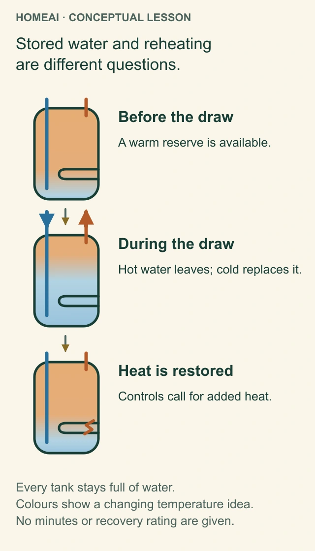
Before the draw
A storage heater holds water that has been heated. The warm tint is a conceptual temperature region, not an exact measured volume.
During the draw
Hot water leaves and incoming cold water replaces it. Closely spaced uses can draw on the stored reserve while the heater adds heat within its operating capability.
Heat restored
The controls determine when heat is added. Element sequencing, burner operation and recovery depend on the actual model; the drawing supplies no cycle timing.
Full vessel
The tank is full in all three views. The changing colours do not depict an emptying tank, a movable partition or a prescribed temperature profile.
Explore the named parts
- Before the draw
A storage heater holds water that has been heated. The warm tint is a conceptual temperature region, not an exact measured volume.
- During the draw
Hot water leaves and incoming cold water replaces it. Closely spaced uses can draw on the stored reserve while the heater adds heat within its operating capability.
- Heat restored
The controls determine when heat is added. Element sequencing, burner operation and recovery depend on the actual model; the drawing supplies no cycle timing.
- Full vessel
The tank is full in all three views. The changing colours do not depict an emptying tank, a movable partition or a prescribed temperature profile.
Stored water and reheating are different questions.
Stored reserve, incoming cold water and added heat. Water use and reheating occur within a filled vessel. Tank volume and the rate at which heat can be restored are different characteristics.
- Before the draw
- A storage heater holds water that has been heated. The warm tint is a conceptual temperature region, not an exact measured volume.
- During the draw
- Hot water leaves and incoming cold water replaces it. Closely spaced uses can draw on the stored reserve while the heater adds heat within its operating capability.
- Heat restored
- The controls determine when heat is added. Element sequencing, burner operation and recovery depend on the actual model; the drawing supplies no cycle timing.
- Full vessel
- The tank is full in all three views. The changing colours do not depict an emptying tank, a movable partition or a prescribed temperature profile.
Read all the diagram text
- HOMEAI · CONCEPTUAL LESSON
- Stored water and reheating are different questions.
- Before the draw
- A warm reserve is available.
- During the draw
- Hot water leaves; cold replaces it.
- Heat is restored
- Controls call for added heat.
- Every tank stays full of water.
- Colours show a changing temperature idea.
- No minutes or recovery rating are given.
- Stored water and reheating
- are different questions.
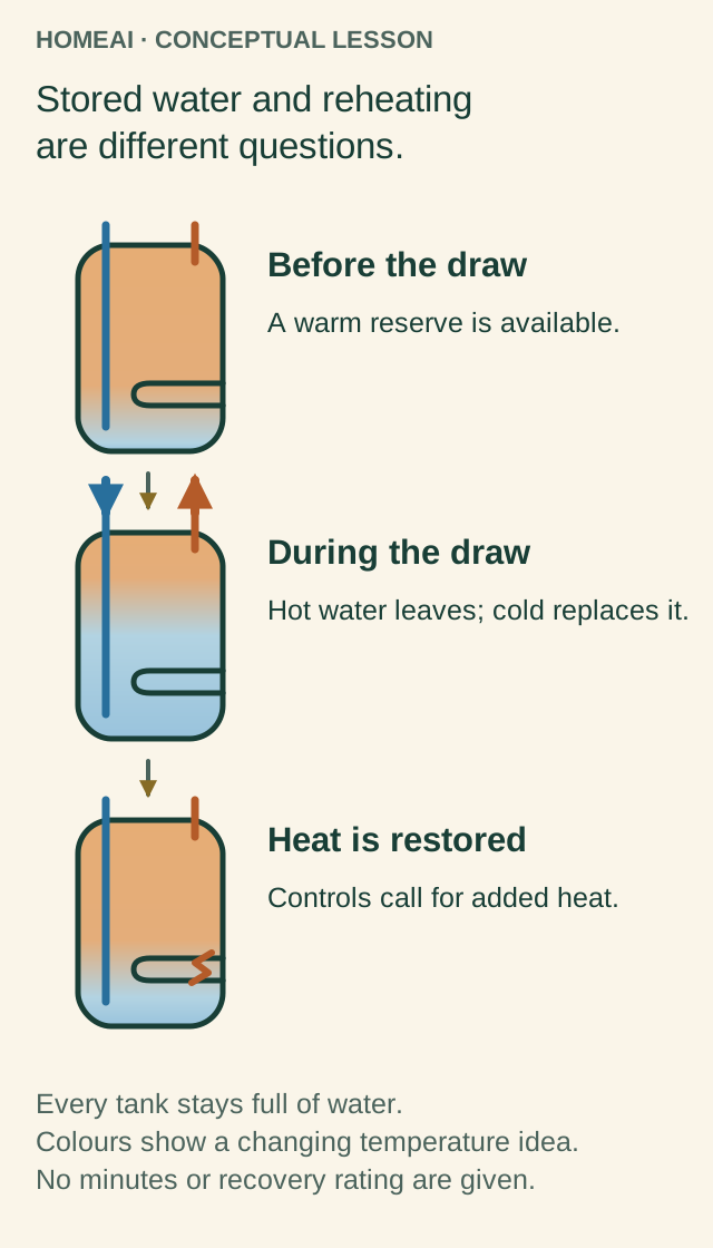
When hot water leaves a normally supplied tank, incoming water replaces it. The tank does not intentionally empty to an air gap and then wait to refill. As colder water enters and heat is drawn away, the controls call for heating according to that design. The three-stage diagram separates a ready reserve, a continuing draw and recovery; its stages are concepts, not a prediction of minutes or exact temperature layers.
For a service conversation, describe when delivery changed and which ordinary uses had just occurred. Include whether this is a recent change or a long-standing limitation. Size, incoming water temperature, heating capability, controls and other faults can all matter. Buying a larger-looking tank before those questions are separated may leave the original problem unanswered.
Sources for this chapter
How does a gas tankless heater warm passing water?
A tankless unit has a heat exchanger instead of the same storage-tank reserve. In the reviewed condensing-gas example, water movement is detected by a flow sensor. The controller coordinates the fan, gas valves and ignition; heat from the burner crosses the heat-exchanger surfaces into the flowing water. Temperature sensors help the controls manage output while water is moving.
Two exchangers, a burner and a fan
Upper secondary exchanger, middle primary exchanger, dry burner and fan perform different jobs. The metal assemblies enclose water channels; the paired route diagram follows water, combustion gases and condensate separately. This is a component-recognition study with partial connections, rather than a complete installed piping layout.
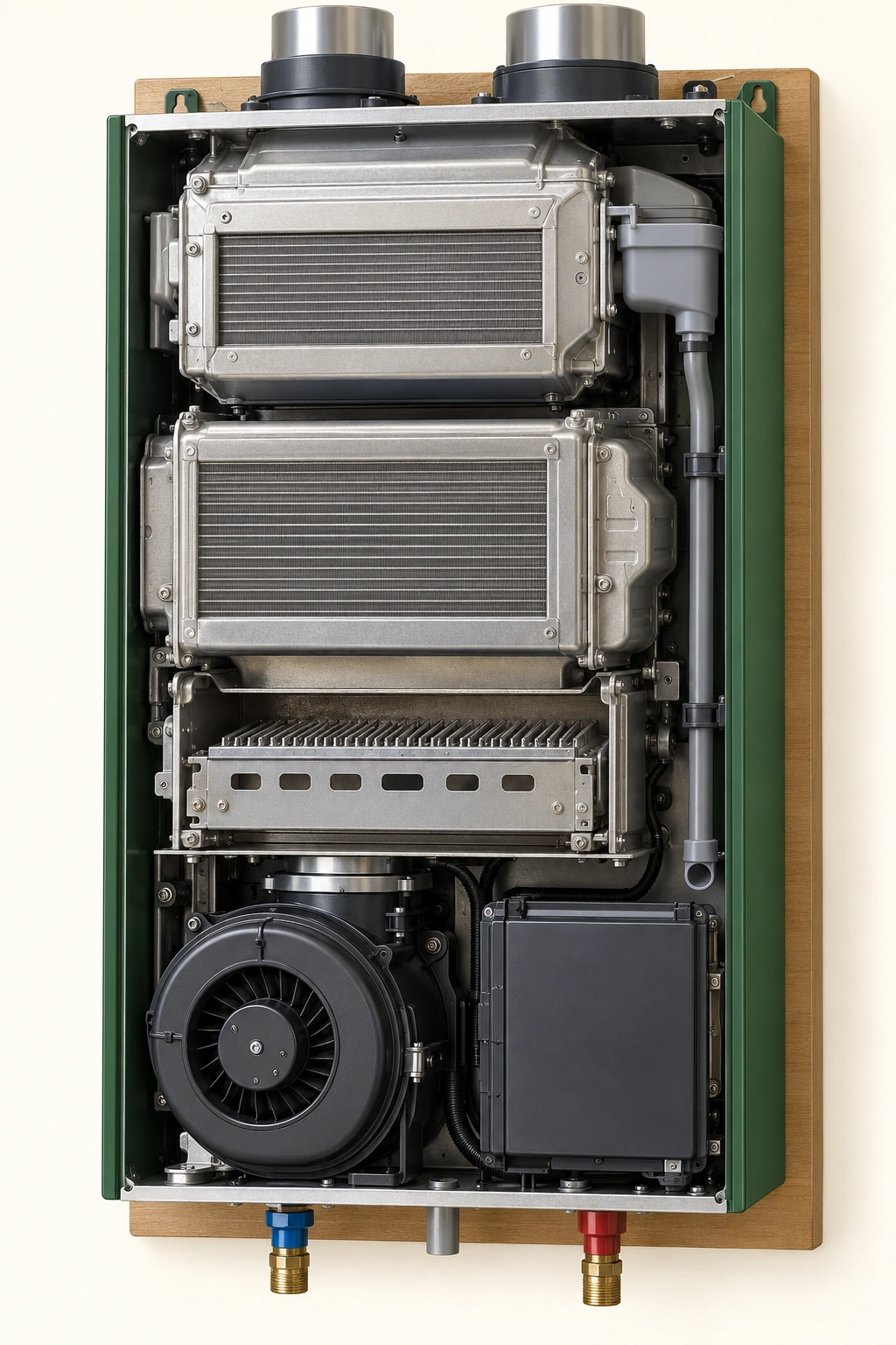
Upper secondary exchanger
This upper assembly represents the extra heat-recovery job in the condensing concept. Its hidden water channels are not traced in this picture.
Middle primary exchanger
The primary assembly transfers burner heat across metal surfaces to passing water. Use the separate mechanism diagram for the complete conceptual sequence.
Dry burner
The burner is below the primary exchanger in this example. Combustion and household water belong on separate sides of heat-transfer surfaces.
Lower fan
The separate fan belongs to the combustion-air system. Neither a fan’s appearance nor this generic component picture establishes operation or a property finding.
Explore the named parts
- Upper secondary exchanger
This upper assembly represents the extra heat-recovery job in the condensing concept. Its hidden water channels are not traced in this picture.
- Middle primary exchanger
The primary assembly transfers burner heat across metal surfaces to passing water. Use the separate mechanism diagram for the complete conceptual sequence.
- Dry burner
The burner is below the primary exchanger in this example. Combustion and household water belong on separate sides of heat-transfer surfaces.
- Lower fan
The separate fan belongs to the combustion-air system. Neither a fan’s appearance nor this generic component picture establishes operation or a property finding.
The example also has a secondary heat exchanger that recovers more heat from exhaust gases. That process produces condensate requiring its own drainage arrangement. The combustion intake, exhaust and condensate route therefore have different jobs from the cold inlet and hot outlet. This is one gas-condensing example, not the internal layout of every tankless unit or an electric tankless heater.
Water and combustion gases follow separate routes
Cold water, heated water, combustion gases and condensate have different routes. This named-manual-inspired concept keeps them distinct; dashed cross-wall arrows mark heat transfer rather than fluid mixing.
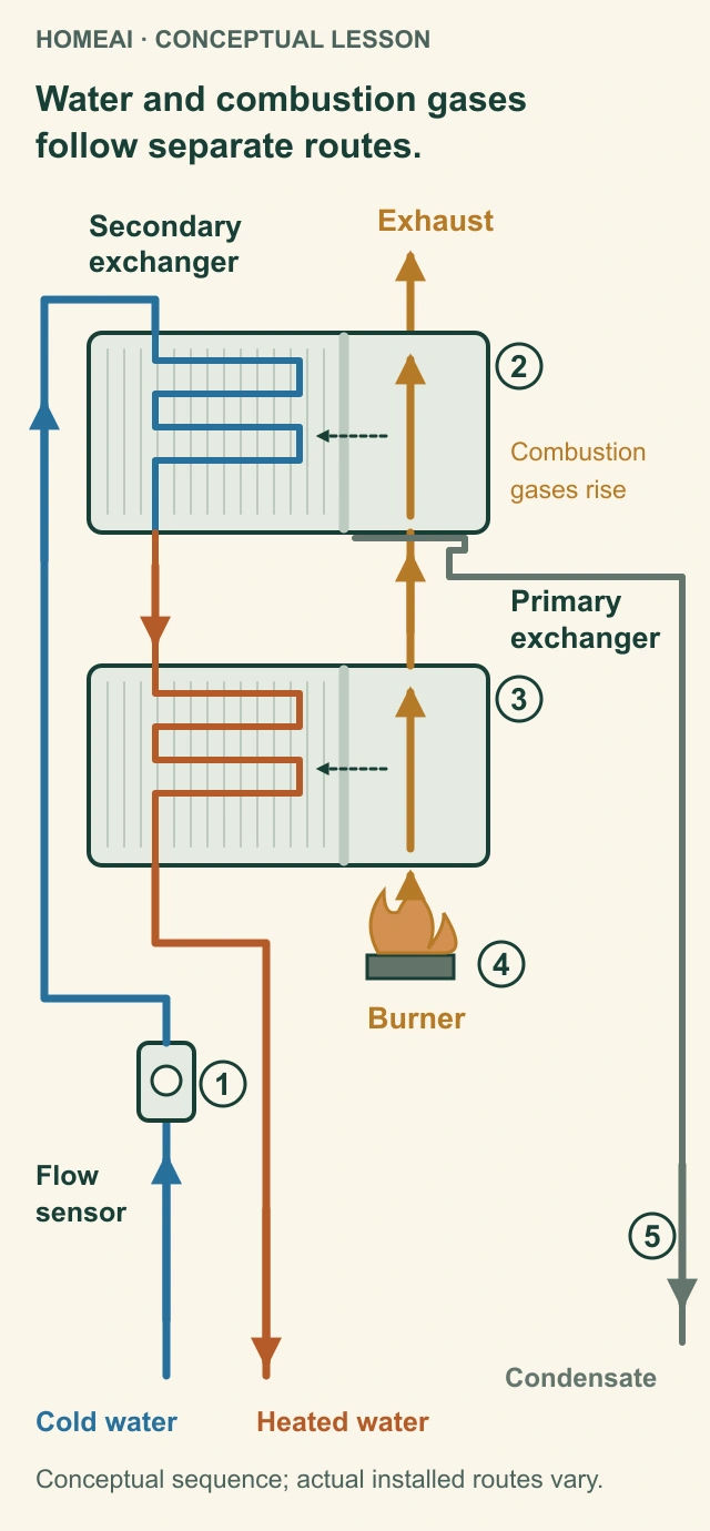
Flow sensor
Water movement is detected before heating is coordinated. The sensor symbol supplies no diagnostic test.
Secondary exchanger
In this concept, incoming water receives exhaust heat before passing to the primary exchanger. Water remains inside its separate channel.
Primary exchanger
Burner gases add heat across metal surfaces to passing water. The dashed arrows represent heat, not gas entering water.
Burner and exhaust
Combustion occurs on the dry side, and gases continue toward exhaust. The appliance’s actual air and gas arrangements need their own scope.
Condensate
Gas-side collected liquid has its own drain, separate from household water. No installed trap, termination or servicing procedure is specified.
Explore the named parts
- Flow sensor
Water movement is detected before heating is coordinated. The sensor symbol supplies no diagnostic test.
- Secondary exchanger
In this concept, incoming water receives exhaust heat before passing to the primary exchanger. Water remains inside its separate channel.
- Primary exchanger
Burner gases add heat across metal surfaces to passing water. The dashed arrows represent heat, not gas entering water.
- Burner and exhaust
Combustion occurs on the dry side, and gases continue toward exhaust. The appliance’s actual air and gas arrangements need their own scope.
- Condensate
Gas-side collected liquid has its own drain, separate from household water. No installed trap, termination or servicing procedure is specified.
Water and combustion gases follow separate routes
Cold water, heated water, combustion gases and condensate have different routes. This named-manual-inspired concept keeps them distinct; dashed cross-wall arrows mark heat transfer rather than fluid mixing.
- Flow sensor
- Water movement is detected before heating is coordinated. The sensor symbol supplies no diagnostic test.
- Secondary exchanger
- In this concept, incoming water receives exhaust heat before passing to the primary exchanger. Water remains inside its separate channel.
- Primary exchanger
- Burner gases add heat across metal surfaces to passing water. The dashed arrows represent heat, not gas entering water.
- Burner and exhaust
- Combustion occurs on the dry side, and gases continue toward exhaust. The appliance’s actual air and gas arrangements need their own scope.
- Condensate
- Gas-side collected liquid has its own drain, separate from household water. No installed trap, termination or servicing procedure is specified.
Read all the diagram text
- HOMEAI · CONCEPTUAL LESSON
- Water and combustion gases follow separate routes.
- Exhaust
- Secondary exchanger
- Primary exchanger
- Burner
- Combustion gases rise
- Flow sensor
- Cold water
- Heated water
- Condensate
- Conceptual sequence; actual installed routes vary.
- 1
- 2
- 3
- 4
- 5
- Water and combustion gases
- follow separate routes.
- Secondary
- exchanger
- Primary
- Combustion
- gases rise
- Flow
- sensor
“On demand” does not mean unlimited simultaneous delivery. The model's capability depends on flow and the temperature rise required between incoming and outgoing water. Several uses at once can exceed what a particular unit can supply. A catalogue maximum without its temperature conditions is an incomplete comparison, especially when incoming water changes seasonally.
A tankless arrangement can suit a home where avoiding a large storage vessel matters. It heats passing water, but still needs capacity matched to concurrent demand and incoming water conditions. The illustrated gas-condensing type also needs appropriate fuel, air, exhaust and condensate arrangements, along with model-specific filter and heat-exchanger care. “Tankless” changes the equipment and service questions; it does not make hot water arrive instantly at a distant tap.
Sources for this chapter
Why can one tap be slow while another runs out of hot water?
Water already standing in a hot-water pipe can cool between uses. When you open the tap, that water has to move before hotter water from the appliance arrives. The route's length and pipe size help explain this delay. Changing the heater does not automatically remove water waiting in the distribution pipe.
A tankless unit also has model-specific conditions for starting and continuing heating. A low-flow complaint is therefore a different question from a storage tank's reserve being used up. Tell the provider whether the concern is a long initial wait, a temperature change during use or inadequate delivery when another fixture starts. There is no need to recreate a fault or run a household stress test to make that description useful.
If only one shower behaves differently, ask about that fixture's mixing arrangement as well as the heater. If several fixtures change together, say so. Where a circulation return exists, its controls and route may be relevant; the circulation guide explains that system. These observations narrow the assignment, but they do not identify a failed valve, element or heat exchanger by themselves.
Sources for this chapter
What are sediment, scale and the anode doing?
Sediment is material that collects at the bottom of a tank. Mineral scale is a deposit that can build up on surfaces such as heating elements. They are related maintenance questions with different locations: a tank-bottom deposit and an encrusted element are not the same part or finding. The close-ups make those differences visible without suggesting that the household should open the equipment.
Deposits and a consumed anode are different conditions
Tank-bottom sediment, scale on an element and a consumed sacrificial anode belong to different service questions. These magnified illustrations make the parts and possible appearances recognizable; they do not establish deposit composition, an actual amount, elapsed age or remaining life. Ask what was examined and what the service provider actually found.
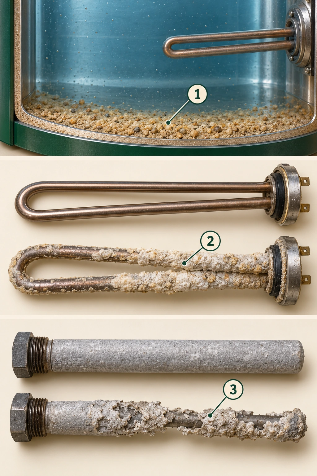
1 · Tank-bottom material
Loose granular material illustrates sediment settling in the lower vessel. The visible water fills the cropped view; no water level, measured quantity or universal deposit texture is shown.
2 · Element deposit
The partly encrusted element is distinct from the clean reference beside it. This is a part-recognition comparison, not two dated photographs, an instruction to remove the element or a diagnosis from a sound.
3 · Sacrificial anode
Where a sacrificial anode is used, its material can be consumed while helping protect the tank. These two illustrative rods show that job, not a replacement threshold, actual inspection or promised service interval.
Explore the named parts
- 1 · Tank-bottom material
Loose granular material illustrates sediment settling in the lower vessel. The visible water fills the cropped view; no water level, measured quantity or universal deposit texture is shown.
- 2 · Element deposit
The partly encrusted element is distinct from the clean reference beside it. This is a part-recognition comparison, not two dated photographs, an instruction to remove the element or a diagnosis from a sound.
- 3 · Sacrificial anode
Where a sacrificial anode is used, its material can be consumed while helping protect the tank. These two illustrative rods show that job, not a replacement threshold, actual inspection or promised service interval.
The reviewed electric and heat-pump manuals connect deposits with water hardness and other operating conditions. A new sound alone cannot tell you how much deposit is present or which task will resolve it. Ask what the provider actually observed, where they observed it and how that relates to the complaint. Record a completed task separately from an assumed cause.
A sacrificial anode serves a different purpose again: it is consumed while helping protect a tank design that uses it against corrosion. A service note saying “flushed” does not establish that the anode was examined. Ask whether its condition was assessed, whether it was replaced and which approved component was used.
Water treatment can affect the discussion. The named electric and heat-pump manuals describe faster anode depletion with softened water. That is a reason to tell the provider which treatment equipment exists, not an instruction to install or remove a softener. Keep relevant water results with their date, units and sample location. Let the actual model's instructions and conditions determine care rather than adopting a national flushing interval or a promised lifespan.
Sources for this chapter
Why is the heater setting different from the water at a tap?
The heater control tells the appliance what it is trying to achieve. Water delivered at a fixture has also travelled through piping and may have passed through a mixing device. A thermostatic mixing valve combines hot and cold water to limit the temperature delivered along its intended route. Its presence, position and function matter; a controller display is not a measurement at every shower.
A heater setting is not a measured tap result.
Heater control, mixing protection and fixture. These are different parts of the hot-water arrangement. Identify what is actually fitted and ask which delivery locations and conditions a qualified assessment covered.
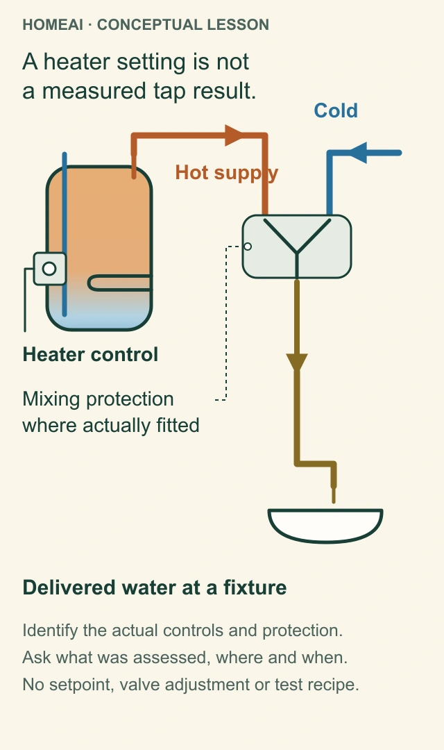
Heater control
A control’s intended setting is separate from a temperature measured at a particular fixture. This diagram does not prescribe a setting.
Hot and cold routes
The two incoming lines stay distinct until the mixing symbol. Their colours are conceptual rather than evidence about an actual pipe or temperature.
Mixing protection
The symbol identifies the job of combining hot and cold water where an appropriate device is actually fitted. It does not establish a required layout or suitable device for a property.
Delivered water
An assessment must identify its fixture, conditions and protection scope. The diagram gives no adjustment, homeowner temperature test or assurance that a displayed setting controls every outlet.
Explore the named parts
- Heater control
A control’s intended setting is separate from a temperature measured at a particular fixture. This diagram does not prescribe a setting.
- Hot and cold routes
The two incoming lines stay distinct until the mixing symbol. Their colours are conceptual rather than evidence about an actual pipe or temperature.
- Mixing protection
The symbol identifies the job of combining hot and cold water where an appropriate device is actually fitted. It does not establish a required layout or suitable device for a property.
- Delivered water
An assessment must identify its fixture, conditions and protection scope. The diagram gives no adjustment, homeowner temperature test or assurance that a displayed setting controls every outlet.
A heater setting is not a measured tap result.
Heater control, mixing protection and fixture. These are different parts of the hot-water arrangement. Identify what is actually fitted and ask which delivery locations and conditions a qualified assessment covered.
- Heater control
- A control’s intended setting is separate from a temperature measured at a particular fixture. This diagram does not prescribe a setting.
- Hot and cold routes
- The two incoming lines stay distinct until the mixing symbol. Their colours are conceptual rather than evidence about an actual pipe or temperature.
- Mixing protection
- The symbol identifies the job of combining hot and cold water where an appropriate device is actually fitted. It does not establish a required layout or suitable device for a property.
- Delivered water
- An assessment must identify its fixture, conditions and protection scope. The diagram gives no adjustment, homeowner temperature test or assurance that a displayed setting controls every outlet.
Read all the diagram text
- HOMEAI · CONCEPTUAL LESSON
- A heater setting is not a measured tap result.
- Heater control
- Hot supply
- Cold
- Mixing protection where actually fitted
- Delivered water at a fixture
- Identify the actual controls and protection.
- Ask what was assessed, where and when.
- No setpoint, valve adjustment or test recipe.
- A heater setting is not
- a measured tap result.
- Mixing protection
- where actually fitted
Scald prevention and control of harmful bacterial growth are both important. Public Health Agency of Canada guidance discusses heater storage and mixing protection together. Simply lowering every control or making delivery hotter does not assess the complete arrangement. Ask a qualified provider to reconcile the actual heater, mixing protection, household needs and applicable local requirements.
A useful assessment says what was read or measured, where, in which units and under what operating conditions. Keep heater settings, mixing-device identity and delivery findings distinct. Do not open concealed thermostats, defeat a limiter or experiment with hotter water. This guide supplies no universal temperature target or setting procedure, and a picture cannot establish a household's infection risk.
Sources for this chapter
What does a display message or operating mode tell you?
A display can show a set temperature, an operating state or a fault indication, depending on the product. The Voltex AL manual distinguishes heat-pump, hybrid and electric modes; the reviewed tankless manual distinguishes controller information and fault indications. Those meanings belong to the named model. Similar icons or numbers on another appliance can mean something different.
If an externally visible message appears during ordinary access, record its exact wording or number and the time. Note the ordinary-use context without opening equipment or entering installer menus. Keep that observation separate from the technician's diagnosis. A code is a useful starting point for the model's troubleshooting process, rather than automatic proof that one named part must be replaced.
Ask how household controls should normally be used, what changes require advice and which messages call for service. Keep that explanation with the matching manual. Repeated resets can erase the sequence you were trying to describe; do not use them to keep suspect equipment operating or to make a message disappear.
Sources for this chapter
Which signs need service, and when should you leave immediately?
A CO alarm takes priority over the heater investigation. Leave the home immediately for fresh air, do not try to find the source, and call emergency services from outside. Return only after professionals have resolved the problem. CO cannot be seen or smelled, so the absence of an unusual odour does not settle that risk.
If you smell gas, leave without trying to light equipment or operating electrical switches. Contact the gas supplier's emergency service or fire department from outside. Smoke, fire or an immediate danger also takes priority over collecting a photograph. Stay clear of wet electrical equipment and obtain urgent help; do not reach through water to a heater control or cover.
For a non-emergency service concern, describe what you can safely see: wetness at a top connection, water in a drain pan, corrosion on an accessible fitting, an unfamiliar message or changed delivery. A leak can come from piping, an appliance connection or another source. Do not conclude that the tank wall failed from the location of a puddle alone.
Wet connection and water in a pan are useful observations
External connection and collection pan. The upper view makes a wet joint and nearby surface deposit recognizable; the lower view shows water collected beside the tank. These are illustrative observations, not a diagnosis that the tank wall failed. Stay clear of hot water and wet electrical equipment, and describe the location to the service provider.
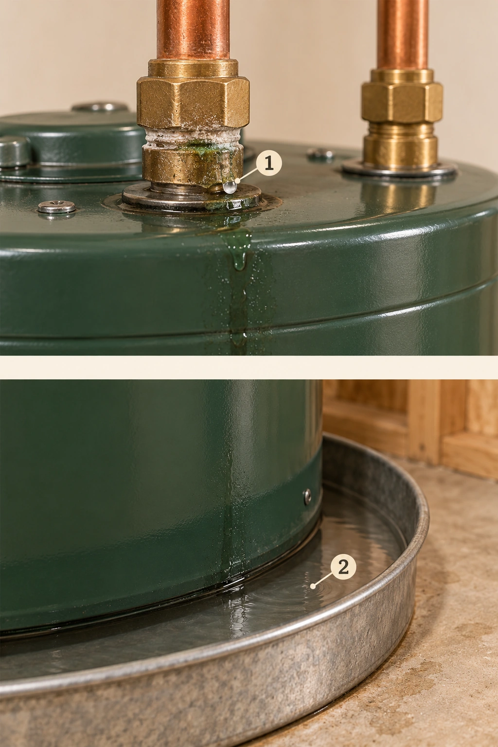
1 · Changed connection
A bead, wet trail or changed surface at an accessible joint is something to describe. The picture cannot identify deposit chemistry, establish an internal fault or prescribe tightening the fitting.
2 · Water in the pan
Water beside a tank can come from more than one source. These two views do not establish one verified leak route or show a universal pan installation. A qualified assessment should identify the source and the appropriate response.
Explore the named parts
- 1 · Changed connection
A bead, wet trail or changed surface at an accessible joint is something to describe. The picture cannot identify deposit chemistry, establish an internal fault or prescribe tightening the fitting.
- 2 · Water in the pan
Water beside a tank can come from more than one source. These two views do not establish one verified leak route or show a universal pan installation. A qualified assessment should identify the source and the appropriate response.
Keep clear of hot discharges. A relief valve provides a protective escape route for specified pressure or temperature conditions. Never cap its discharge, plug the valve or defeat the protection to stop water appearing. Tell the service provider where water is escaping; the cause and complete discharge arrangement need assessment. The leak guide helps describe other wet-area observations without approaching suspect equipment.
Sources for this chapter
What care belongs in a model-specific plan?
Start with the correct manual, then ask which tasks apply to the installed arrangement. A storage tank raises water-side, anode and protective-component questions. A gas model adds combustion-air, burner and vent questions. A heat-pump model adds its air filter, air route and condensate components. A condensing tankless unit has its own inlet-filter, heat-exchanger, exhaust and condensate concerns.
Those are different jobs, so one generic service label can hide important omissions. Ask who is responsible for each task, what access it needs and what conditions affect its timing. Water quality, use and manufacturer requirements can change the plan. Keep the basis for the next review, not just a recurring calendar alert.
Some manuals describe tasks that involve hot pressurised water, exposed electrical parts or gas controls. Reading about a component does not make opening or testing it a safe household task. Arrange the appropriate qualified service. This guide does not provide draining, relief testing, descaling, chemical treatment, wiring, ignition or combustion-adjustment instructions.
Sources for this chapter
Which manual and dates should you keep?
Match the exact manufacturer and model to the applicable manual edition. Manufacturers can retain both current and discontinued product documents, and a familiar-looking cover does not establish a match. Keep the original manual link or file and the equipment identity together. The model and serial are useful to the manufacturer when confirming a document or part.
Separate manufacture, purchase, installation and service dates. An invoice records its own work date; it does not necessarily establish when an older heater was first installed. If a date is uncertain, say what document or person supplied it. Avoid turning an unofficial serial-number chart into a confirmed installation date.
Keep installation and commissioning records, relevant completion documents, warranty terms and the service contact. Where equipment is rented or financed, establish who authorizes work before arranging a replacement. The inherited-equipment agreements guide covers that contract question. A warranty term or account statement is still a different record from the findings of a service visit.
Sources for this chapter
What should a useful service record actually say?
A useful record connects the visit to the appliance: model identity, visit date, the concern reported and the agreed work. It then names tasks completed, findings observed, parts addressed and the verification performed. “Water-heater service” tells a future provider much less than a description that distinguishes an inlet-filter task from a delivery-temperature assessment.
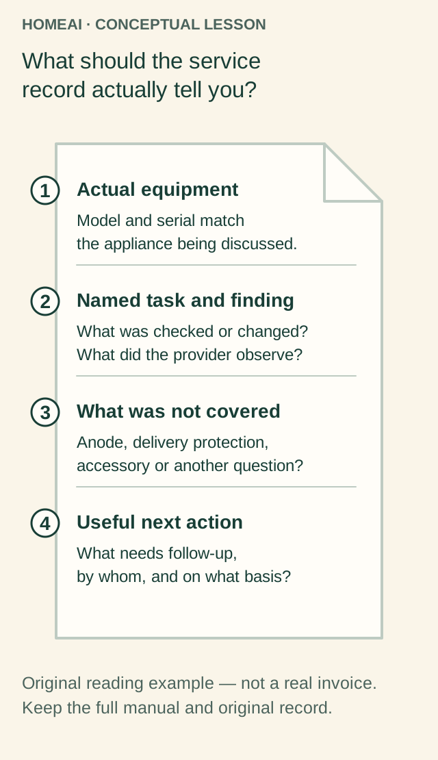
What should the service record actually tell you?
Equipment identity, completed task, findings and remaining scope. A useful record explains what happened at this appliance rather than relying on the words annual service alone.
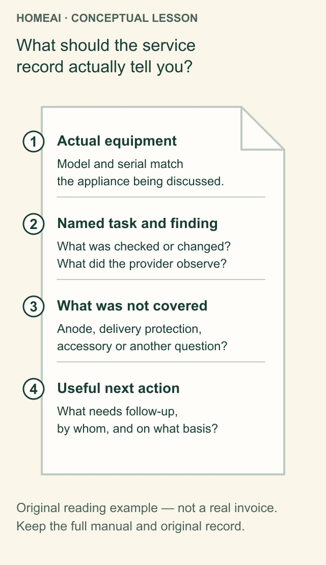
Actual equipment
Match the model and serial to the appliance being discussed and the applicable manual. Installation date, manufacture date and visit date answer different questions.
Task and finding
Ask which component or task was covered, what was observed, and what work was completed. A general heading is less useful than the actual scope.
Not covered
Keep an anode assessment, heater maintenance, delivery protection and linked accessories distinct. A task recorded in one area does not describe everything else.
Next action
Retain the provider’s explanation of follow-up and its basis in the actual equipment and conditions.
Explore the named parts
- Actual equipment
Match the model and serial to the appliance being discussed and the applicable manual. Installation date, manufacture date and visit date answer different questions.
- Task and finding
Ask which component or task was covered, what was observed, and what work was completed. A general heading is less useful than the actual scope.
- Not covered
Keep an anode assessment, heater maintenance, delivery protection and linked accessories distinct. A task recorded in one area does not describe everything else.
- Next action
Retain the provider’s explanation of follow-up and its basis in the actual equipment and conditions.
What should the service record actually tell you?
Equipment identity, completed task, findings and remaining scope. A useful record explains what happened at this appliance rather than relying on the words annual service alone.
- Actual equipment
- Match the model and serial to the appliance being discussed and the applicable manual. Installation date, manufacture date and visit date answer different questions.
- Task and finding
- Ask which component or task was covered, what was observed, and what work was completed. A general heading is less useful than the actual scope.
- Not covered
- Keep an anode assessment, heater maintenance, delivery protection and linked accessories distinct. A task recorded in one area does not describe everything else.
- Next action
- Retain the provider’s explanation of follow-up and its basis in the actual equipment and conditions.
Read all the diagram text
- HOMEAI · CONCEPTUAL LESSON
- What should the service record actually tell you?
- 1 Actual equipment
- Model and serial match the appliance being discussed.
- 2 Named task and finding
- What was checked or changed? What did the provider observe?
- 3 What was not covered
- Anode, delivery protection, accessory or another question?
- 4 Useful next action
- What needs follow-up, by whom, and on what basis?
- Original reading example — not a real invoice.
- Keep the full manual and original record.
- What should the service
- record actually tell you?
- 1
- Actual equipment
- Model and serial match
- the appliance being discussed.
- 2
- Named task and finding
- What was checked or changed?
- What did the provider observe?
- 3
- What was not covered
- Anode, delivery protection,
- accessory or another question?
- 4
- Useful next action
- What needs follow-up,
- by whom, and on what basis?
Keep completed work and recommended work in separate fields. If an accessory, fixture, vent section or inaccessible area was outside the assignment, retain that exclusion. Ask what remains unanswered and who should handle it. An anode replacement is valuable information, but it does not mean every pipe, control, mixing valve and combustion component was assessed.
Record measurements with units, location and conditions rather than a bare number. Retain the reason for the next care review and a contact for a returning concern. The annotated record is a teaching example of useful fields. You can use those fields to request a clearer copy of your actual service documentation.
Sources for this chapter
What should you ask before replacement or a new-home handover?
Before choosing a replacement, ask what explains the current complaint and what the proposed change will address. Capacity, heating capability and distribution are separate questions. A recommendation should identify the actual equipment, household demand considered and associated work, rather than promise that a bigger tank or tankless cabinet will solve every hot-water concern.
A change in heater type can also change the assignment around it: electrical supply, combustion-air and venting arrangements, air access, condensate disposal or controls may need review. Ask the appropriate professionals to identify the scope, local requirements and completion records. Do not use a conceptual picture as an installation plan or a parts-shopping list.
For a new home, ask for the installed model's instructions, commissioning and relevant completion records, an explanation of household controls and the route for reporting concerns. Preserve the previous appliance's history separately after replacement. The aim is practical: understand how this heater supplies your home, recognize when to seek help, and leave the next service provider with a clearer starting point.
Sources for this chapter
Keep learning about the connected parts
- Hot-water recirculation: follow the supply, return and controls
- Water leaks explained: find the right question before the repair
- Water softeners: understand service, regeneration and the limits
- Inherited equipment agreements: identify what transfers
- Build a home-care record that the next person can understand
- Apartment water systems: risers, central hot water and shared response
Canadian context and authorities · Visual atlas · Learning labs
Know the parts.
Know what the words mean.
- Storage heater
- A heater that keeps a reserve of heated water in a tank.
- Recovery
- Restoring heat to stored water after use.
- Dip tube
- An internal tube that carries incoming water low in the illustrated top-inlet tank arrangement.
- Immersion element
- An electric heating part extending into the water.
- Sacrificial anode
- A component consumed while helping protect a tank design that uses it against corrosion.
- Outer jacket
- The outer casing around the insulated tank assembly.
- Flue
- The intended passage for combustion gases through the illustrated gas-heater design.
- Heat exchanger
- Surfaces that transfer heat between routes while keeping their fluids separate.
- Condensate
- Liquid collected when water vapour condenses; it needs its intended drainage route.
- Temperature rise
- The difference between incoming and intended outgoing water temperatures.
- Thermostatic mixing valve
- A device that combines hot and cold water to limit delivered temperature along its intended route.
- Service scope
- The equipment, tasks, observations and checks included in an agreed visit.
- Refrigerant
- The working fluid in the heat-pump circuit that carries transferred heat.
- Evaporator
- The air-side heat exchanger where refrigerant absorbs heat in this heating explanation.
- Condenser
- The heat exchanger where refrigerant gives up heat to the water in this heating explanation.
- Expansion device
- The heat-pump component that lowers refrigerant pressure and temperature before it absorbs heat again.
- Anode
- A sacrificial component used in applicable storage designs to help reduce tank corrosion.
- Model-matched manual
- Manufacturer instructions verified as applicable to the actual product and relevant edition.
- Tankless heater
- An appliance that adds heat to water passing through it within its documented operating capability.
- Temperature set point
- The control’s intended setting, separate from a measured temperature at a named fixture.
Questions to bring
to the conversation.
- What heater and energy arrangement does the actual model identify?
- Did the change affect one fixture or several, and during what ordinary use?
- Which water, air, vent, condensate and protective components belong to the service assignment?
- Does the record distinguish completed tasks, findings, measurements and exclusions?
- Who will address a returning concern or explain the next model-specific care review?
Separate a showing observation, an existing record and a new professional assessment. Unknown means a question remains; it does not automatically mean a defect.
Use the evidence planner ↗Go to the source.
Original HomeAI explanation informed by these public references. Sources support the underlying guidance; they have not reviewed or endorsed HomeAI. Diagrams are conceptual, and calculator outputs depend on your inputs.
Canadian education and named manufacturer examples explain the parts together. Actual model instructions, water conditions and local requirements govern the service assignment.
Publication & source review
First published .
Sources reviewed .
- Natural Resources Canada · Guide to residential water heaters
- Natural Resources Canada · Water Heater Guide
- GIANT · Residential Electric Water Heater owner manual
- GIANT · Residential Gas Water Heaters installation/use and care guide
- A. O. Smith / Voltex AL · Hybrid Electric Heat Pump Water Heater installation/use and care
- GSW · Condensing Gas Tankless installation manual and owner guide
- Public Health Agency of Canada · Water temperature and burns/scalds
- Health Canada · Carbon monoxide: preventing exposure
- A. O. Smith · What is a heat pump water heater?
- Natural Resources Canada · Heat Pump Technologies fact sheet
Have a question about your home?
Start with the symptom, timing and what you have observed.
Ask HomeAI